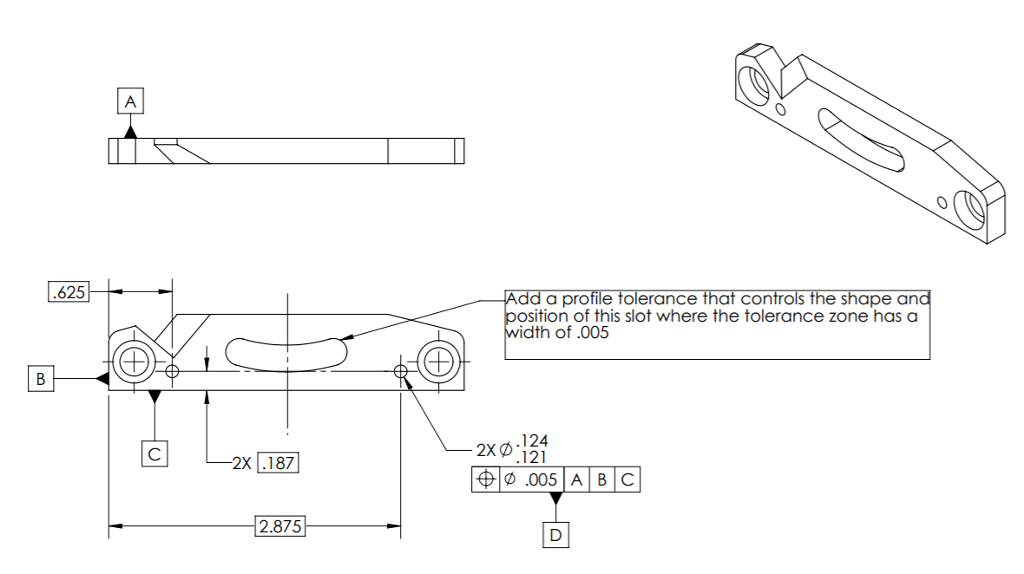
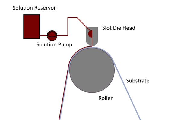
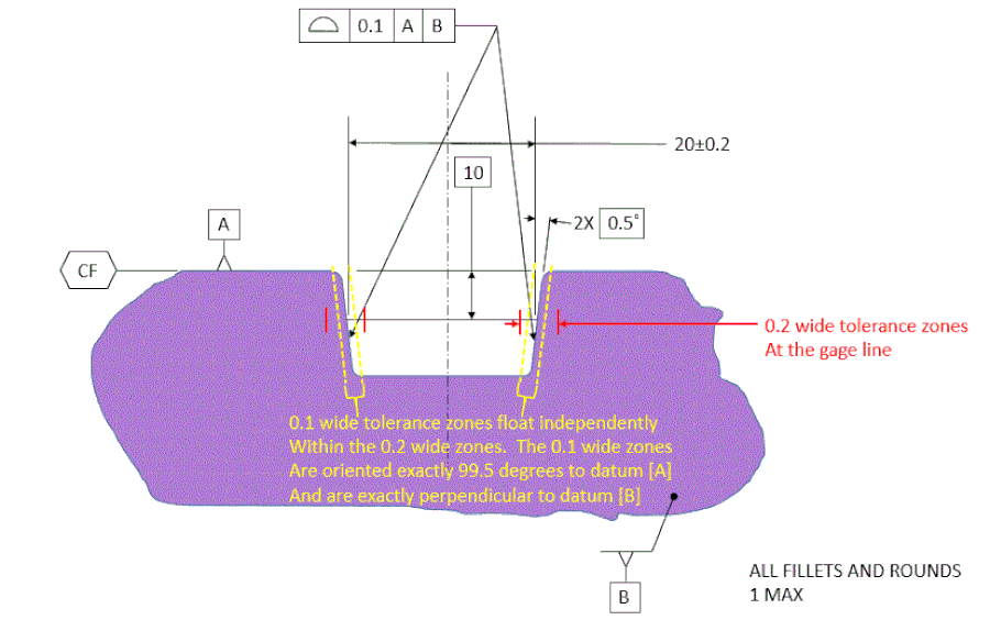
Slot Profile Tolerance
Assure Proper Manufacturing of Your Printed Circuit Boards
Advanced Circuits provides you below with the required in-house tolerance guidelines to ensure quality manufacturing of your printed circuit boards. Adhering to these tolerances will allow for proper manufacturing of your PCBs. Within these parameters, there is enough variation to allow us to manufacture the board and then also for it to work properly in your application. If you have any questions or want to discuss unique requirements, please call 1-800-979-4722 to contact us.
Tool Size Tolerance. The tool bits for creating slots are machined and thus have a tolerance on the size as set by the manufacturer. Standard Tool bits used for creating slots have normal tolerance of +0.01/-0.00mm or +0.00/-0.01mm. This may change depending upon the size and function of the tool bit. Tolerancing Techniques (Using the Customary Inch Systems) by Lowell W. Foster. Tolerance design: a handbook for developing optimal specifications by C.M. Dimensioning and Tolerancing Handbook by Paul J. Drake. Inspection and Gaging by Clifford W. Kennedy. Geometric Dimensioning and Tolerancing by Cecil H. That being said, I am thinking of applying two single segment profile of surface tolerance frames, all around, to both subgroups of 5 slots (tolerance values are exmplary, slots geometry and location are assumed to be defined by basic dimensions. 3 Extruded Wire, Rod, Bar and Profiles TABLE 11.2 Cross-Sectional Dimension Tolerances—Profi les Q EXCEPT FOR T3510, T4510, T6510, T73510, T76510 AND T8510 TEMPERS U.
Inner Layer Clearances
We require a minimum of 0.010' inner layer clearance.
Copper to Edge of Printed Circuit Board
Minimum of 0.010' (outer layers) and 0.015' for inner layers (0.020' preferred for inner layers). For scoring, minimum of .015 for outer layers and .020 for inner layers.

Pad Size/Annular Ring
Pad size should be at least + 0.010' over finished hole size for vias and + 0.014' over finished hole size for component holes. This means the annular ring (radius of the pad) should be at least .005' for vias and a minimum of 0.007' for component holes.

Hole Size
+/- 0.005' Standard Spec (applies to holes up to .250', larger holes will be routed, see Rout tolerances below)
+/- 0.005' Custom Spec
+/- 0.003' Custom Spec upon request 1 oz and 2 oz finished copper weight and 3 oz finished copper weight (when starting with 2 oz foil) only.
If your hole tolerances are zero (see below), then Advanced Circuits will assume that you are OK with our default hole tolerance. Our default hole tolerance is listed above.
Example: Customer Drill Chart with Zero Hole Tolerance
Our minimum finished hole size; 0.004'. Call your salesperson if you required a finishedhole size less than 0.004'.
Printed Circuit Board Thickness:
Thickness tolerances may vary 10% (min.+/- 0.005')
Minimum Board Thickness
| Thickness | Default | File Review Req. |
|---|---|---|
| 2-Layer | .020' | .010' |
| 4-Layer | .020' | .015' |
| 6-Layer | .031' | .025' |
| 8-Layer | .047' | .031' |
| 10-Layer | .062' | .040' |
PCB Inner Layer Thickness
Tolerances do not apply to the inner layers of prototypes.
Rout (Board Outline and Internal Cutouts)
The Outer Layer Tolerances on Standard Spec defined boards is +/- 0.010'
(+/- 0.005' available for Custom Spec upon request)
Note: We rout to your board size using the center of the board outline on your mask layer.
Copper Trace Width/Spacing
Copper spacing is the minimum air gap between any two adjacent copper features. Trace width is the minimum width of a copper feature, usually traces.
Requirements: A premium is charged for trace width/spacing less than .007'.
(We can process .004' for 1 oz. CU. finished (outer layers) and .5 oz. CU finished (inner layers).
For 1 oz. finished copper weight (inner layers), the minimum trace width/space is 0.003'
For 2 oz. finished copper weight (inner & outer), the minimum trace width/space is 0.005'
For 3 oz. finished copper weight (inner & outer), the minimum trace width/space is 0.009'
For 4 oz. finished copper weight (inner & outer), the minimum trace width/space is 0.010'
Note: Advanced Circuits does not offer weights such as 1.5 or 2.5 ounce finished on standard and custom spec orders.
Trace Width/Air Gap
The greater of +/- 20% or +/- 0.002'
Soldermask Swell
This is the expansion of mask relief over pad area. Our minimum is 0.005' over pad dimension or 0.0025' each side. Advanced Circuits will modify files to meet the minimum dimension.
Slot Width
Minimum 0.031' in width. For smaller width, call your salesperson for pricing and turntime.

Tab Rout Spacing
Please allow 0.100' spacing between your individual pcbs for tab rout spacing. When scoring there should be no spacing between boards.

Slot Profile Tolerance Tool
Silkscreen (Legend)
Slot Profile Tolerance Meaning
0.005' minimum line width.